
Using a rotator from the 1970's, whilst it is robust and well made, it's very manual !
This project adds the K3NG Arduino based rotator controller to an Emotator 1103MX Rotator controller, to automatically orientate my 6m Yagi towards stations when selected in Log4OM or WSJT-X. This will be achieved using the K3NG sketches, loaded onto an Arduino Mega and PSTRotator will handle the PC connectivity. The K3NG core will also support a Real Time Clock and a Global Positioning System Receiver for Station Time Syncronisation. This core element will be further built upon for routing GPS NMEA Sentences to the TMD-700E for APRS, and another secondary GPS receiving device as well as a shack clock. A later design has also incorporated the build of a Global Heading type display, using a micro servo motor and a custom 3d printed gearbox.
Component Parts
- Manual Rotator Control box
- K3NG Sketches by Radio Artisan
- Arduino Mega 2560
- Adafruit Ultimate GPS
- DS3213 RTC Module
- 4 channel Relay Module
- Adafruit USB Isolator
Rotator Circuit and Modification design
Considerations need to be made for a number of aspects of this design, as the older rotators were not designed to have any additional components and used very wide tolerances compared to the electronic circuits that we are going to integrate with this project. The first issue is that the controller and Rotator motor are based on AC, with some crude rectification for DC, and even cruder DC voltage regulation, but were commonplace in the 1970's, think half wave rectification and reverse Zener Diode voltage regulation.
In the case of the Emotator, this results in a 100v AC Rotator voltage, and 6v DC-ish for the controller to achieve position sensing via a 600Ohm potentiometer, with a shared ground with the 100v AC. The Control box lighting is via 2 bulbs fed with the same 6v DC. The Moving Coil meter is set to display a centre point of N, and from measurements made uses 0 - 200mA for full deviation.
We need to achieve the ability to rotate the antenna, by automation, therefore adding a relay to each of the controller switches is required. There is one for Clockwise, One for Counter-Clockwise and each button has a first stage which is for releasing the brake. Therefore we need 3 relays, and as pre-made modules tend to have 4, we have a spare for something else if we choose to use it. (I had thought of also having a relay on the power switch, but will look at that another time.
We also need to get a feed from the potentiometer to identify the position of the rotator to make control decisions. K3NG gives us a lot of options other than the potentiometer, but using what we have, there is a feed directly from the rear of the existing meter to give us a variable voltage, albeit far too low for accuracy within an arduino 0-5v range.
Finally, we need to think about where the new controller can be housed. Some older controllers have plenty of space within, much as the Emotator has, however the K3NG Arduino Controller is also going to be abases of further shack automation, therefore I am housing it externally so that the follow on projects can be added.
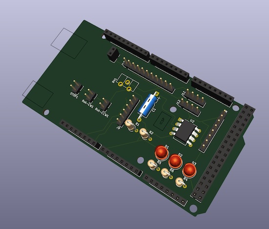
Controller Circuit build
The build of the K3NG is fairly simple, and following the details on the K3NG documentation will get this completed very quickly. Adding the relay boards and configuring these are also very simple to do. Adding additional features can also be achieved but I did run into some issues due to my choice of external components and the initial controller.
Potentiometer Voltage Output
This was in the order of 200mV therefore needed amplification with a suitable circuit. I did not do anything fancy here, just a basic non-inverting Op-Amp based on the MCP6002, as this is a standard 5v rail op-amp and could easily provide the 20 x Gain I needed. I added smoothing caps to the voltage feed, as of the raw nature of the original DC rectification, therefore not needing to use the K3NG signal conditioning software routines.
Adafruit Ultimate GPS
This is an excellent GPS unit and without an external antenna, indoors can pull 7-8 sats to gain a fix. The K3NG code does not natively support this directly, however the set-up of this unit for use on the K3NG controller is easy when you know how !
The GPS module is preset to send sentences in a different format than the code is expecting, and is receiving both GLONASS and GPS for positioning. There are programming commands that are required to do this which are held whilst the GPS has battery backup. I have however added the code to the K3NG codebase so the GPS is initialised every time it restarts to make sure.
Ground Loops
A final issue came once everything was connected up and tested manually, then connecting a USB cable to the Arduino caused the Original controller needle to deflect fully, which was identified as a ground loop. This is easily fixed and I used the Adafruit USB Isolator, and this works well.
K3NG bespoke additions
GPS Initialisation code - This code is added to the main code file, at the bottom of the Setup
You only need to do this every time you remove the GPS board battery, but I just run it every time.
#include <Adafruit_GPS.h>

void setup() {

......

#define GPSSerial Serial2
Adafruit_GPS GPS(&GPSSerial); // allocate serial port
GPSSerial.begin(9600); // connect at 9600
GPS.sendCommand(PMTK_SET_NMEA_UPDATE_1HZ); // 1 Hz update rate
GPS.sendCommand(PMTK_SET_GPS_ONLY);  // Set for GPS only
GPS.sendCommand(PMTK_SET_NMEA_OUTPUT_RMCGGA); // Set updates in correct format

}
Emotator specific settings
//Emotator specific config

#define AZIMUTH_STARTING_POINT_EEPROM_INITIALIZE 0 // North Centre
#define AZIMUTH_ROTATION_CAPABILITY_EEPROM_INITIALIZE 360  // Set for 360 rotation

#define ANALOG_AZ_FULL_CCW_EEPROM_INITIALIZE 40  // Set CCW Voltage reference from debug values, far left
#define ANALOG_AZ_FULL_CW_EEPROM_INITIALIZE 654  // Set CW Voltage reference from debug values, far right
Post build commands issues in Serial Console
These commands cenre the rotator at 0 degrees as indicated on the original Emotator Console.
\X0 (that's Xray Zero)
\I0 (that's India Zero)
\J360
Move rotator to centre, pointing North.
\A360
\Q