Having an MD-200A8X, I rarely need to look at other audio sources. Combined with the majority of radio time these days being on digital modes, I have not had the need to buy additional kit, until now.
Like most of the planet, 2020 didn't really go to plan and I was working from home and replacing endless video conferences and meetings in the office with Microsoft Teams and Amazon Chime calls. Quite frankly the audio on these calls is awful, with a mixture of cheap tinny mic's in laptops and the odd cheap, or sometimes expensive headset that doesn't really represent the voice of the person very well, and being USB isn't terribly useful for anything else. The additional fact that any reasonably priced headset has long gone and is on back order, I thought I'd have something I can use on the radio when I'm back at the office, instead of getting lost in a box somewhere.
I didn't find a cable diagram for a Yaesu 8-pin to XLR cable so have put the following information together in the hope it helps someone else get their BPHS-1 on the air a bit quicker than I did.
I've also added all the homebrew cables I make for my outboard audio connections.
(Yaesu 8-pin) > (XLR) for Headset Direct
(Mixer) > (Attenuator) > (Yaesu) for Xenyx Mixer into Radio.
(XLR) > (Isolator) > (Attenuator) > (Yaesu RCA) for audio isolated connection from Behringer Mixer to Radio.
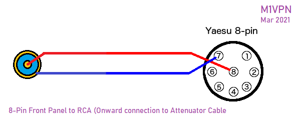
(Yaesu 8-pin) > (RCA Socket) Breakout cable for front mic socket for cable above.
Audio-Technica BPHS-1 direct to Front panel Yaesu 8-pin
The following cable is a alternative to the Heil CC1-XLR-Y8BAL cable, without the PTT in this case, but can be easily added. I've not seen one of these cables to comment on the build quality or anything within the wiring that may be better or worse ? This one works well though, and costs about £5 + your time.
Yaesu 8-pin to XLR
- Neutrik XLR Female Connector
- Yaesu 8-pin Connector
- 2 core plus shield cable
- Heat shrink (preferably not red, it's all I had in that size that was accessible)
Yaesu 8-pin end connections
Pin 8 - Signal +
Pin 7 - Signal -
Route shield to the plug casing by clamping the shield back through the connector. Test for continuity whilst mobilising the cable to ensure good contact.
PTT can be added by placing a switch, or two pole connector between pins 6 (ptt) and 5 (gnd). There have been reports that this can lead to RF breaking into the cable thus I didn't add this feature.
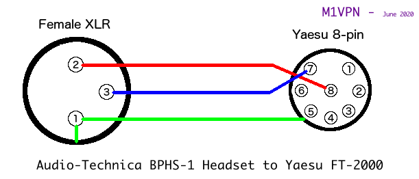
XLR end connections
Pin 1 - Shield that is connected to the 8-pin connector body.
Pin 2 - Signal +
Pin 3 - Signal -
Place wire between XLR connector ground and XLR pin 1.
Note: Disregard the capacitor in the following pictures. This was to prevent RF noise, but it actually created a filter on the audio chain ! Removed in final implementation.
Test shield continuity between XLR Pin 1 and the 8-pin connector body.
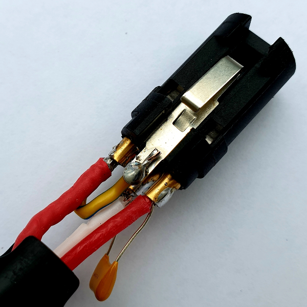
Base of connector showing Shield to Connector ground (excuse the soldering on test connector, still works though)

Top of connector, showing capacitor and top of ground loop. (This soldering is even worse, still works though)
FT-2000 Mic Gain setting - 85, but this may change when the EQ is set up.
Behringer Mixer Output to Yaesu Rear connector (incorporating Line to Mic Level Attenuator - -40dB)
This cable is a 6.35mm mono cable from the mixer to the rear Phono mic connection into the FT-2000. This is expecting a mic level input, whereas the output of the mixer is Line level. A -40db attenuation is required, so a L-pad is created from 2 resistors to drop to a 10th of the originating signal. This should level the microphone input.
In this case, an already terminated cable was purchased, with a Neutrik barrel connector, which has plenty of room inside to hide away two resistors and a capacitor, with careful soldering and heat shrinking.
The final solution is an L-Pad with an 680 Ohm and 68K Ohm resistor, as follows ;
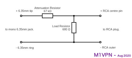
Why a 680 Ohm resistor for the output, well that is the input impedance of the mic connector on the back of the Yaesu FT-2000.
This forms the Pad part of the homebrew isolation box between the Outboard Audio equipment.
This cable did introduce some hum in testing, but I had poor grounding, so Your Mileage May Vary with this, but as the next cable is so easy to make, I'd go for that anyway.
It's not that I didn't want to buy a W2IHY i-box, but I had some bits and pieces and I enjoyed the challenge of building all my other cables. I'm not claiming that my implementation is better, but it was a product of experimentation, which for me is what Amateur Radio is all about, and why I got a licence in the first place.
The basic implementation presents the basic functions of Attenuation and Isolation. The circuit gives -35db attenuation which results in the FT-2000 Mic Gain being 29 with the Behringer Mixer set at 0db on the main output, +4db from the line.
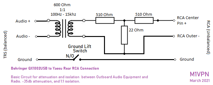
The main purpose for this circuit is to attenuate the signal from the Mixer to the front end of the radio. (Via the Mic port in the rear of the FT-2000, Mic Socket on the FT-847) Isolation between the Radio and the Audio kit, and reduce some Hum and RF being passed into the audio was also a requirement.
The Transformer is rated between 100 Hz to 15 KHz, but may swap it out for something better in time, or re-engineer a DI box.
A note for the FT-2000, the rear port is live with the front port in the menu settings. There should be no need to change anything for the rear port if you are using the front one currently. Both Mic ports are also live, so a mic without PTT will also provide input if you have a mic in the front as well as the rear.
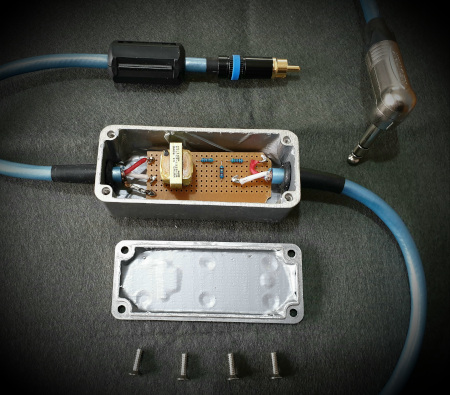
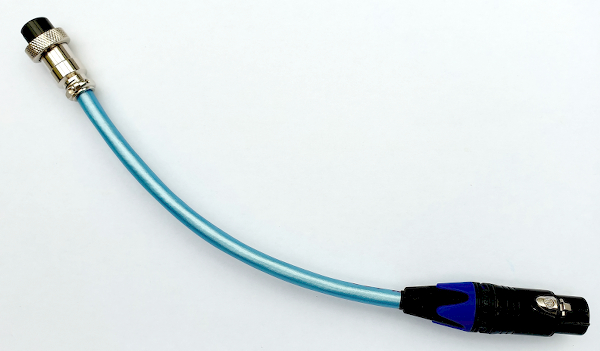
Completed Cable Assembly
8-Pin to RCA Extension Cable (For above)