Uncategorised
Full Results from Contests
(number) after a placing means how many stations were in that category. e.g. 3rd (27)
ARRL 10m Contest (Dec 2025)
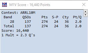
Single Operator, Low Power, Phone Only + Limited Antenna overlay - Unassisted
Contest Notes: F
Yaesu FT-2000, 80m FD4 OCFD Antenna at 12m, Hustler 6BTV, Palstar AT-2K Tuner.
CQ WW DX SSB Contest (Oct 2025)
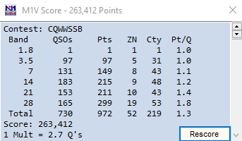
Single Operator, All Bands, Low Power + Classic - Unassisted
Contest Notes: First contest of 2025. Solid contest, although running yielded few Q's. so S+P was order of the day. Some slow periods, but a surprising 10m/15m flurry with the US and South America livened things up a bit. Use of both the OCFD and Hustler vertical, esp the latter on 21 Mhz meant some good contacts.
Not a great score as I didn't maximise on multipliers, but was actively looking for them, however not as easy when running unassisted ! Did pick up China and Rodrigues Island on S+P though.
Yaesu FT-2000, 80m FD4 OCFD Antenna at 12m, Hustler 6BTV, Palstar AT-2K Tuner.
🏆 RSGB FT4 Series 2024
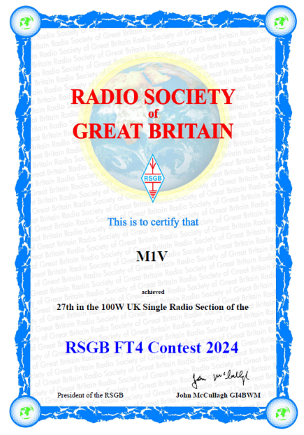
27th (121) - UK 100w Restricted
Single Operator, All Bands
Contest Notes: I only managed to take part in 4 sessions, so placing 27th wasn't too bad.
🏆 WAE RTTY Contest 2024 (9th November 2024)

245th Place (660), 12th England (27)
Single Op, All Bands, Low Power - Unassisted.
235 QSO, 56,156 Pts
Contest Notes: Only a 9 hour entry into this one, as I'd missed contesting over the summer. Not a bad score considering the time on-air. Conditons favoured the low bands, and there were a lot of stations on. Mostly ran for the contest, after an initial S+P. No QTC again this year, but at least was prepared for it, then no one asked !
Yaesu FT-2000, 80m FD4 OCFD Antenna at 12m, Palstar AT-2K Tuner and G4ZLP Interface.
🏆 BARTG Championship 2024 (All BARTG 2024 HF Contests)
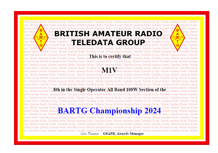
8th Place (608), 3rd England (43) - SOAB 100.
🏆 RSGB FT4 Series - Contest 5 - (17th June 2024)
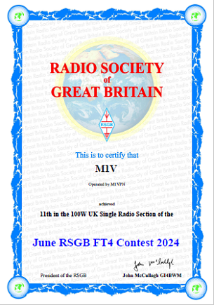
11th (43) - UK 100w Restricted - (310 Series points)
Single Operator, All Bands - 100w (85w)
65 QSO - 1,792 points
Contest Notes: After missing last months session because of holidays, back to a lively band on 15m to start, dropping to 80m. Good Mults count but time management could be better to increase these further.
Yaesu FT-2000, 80m FD4 OCFD Antenna at 12m, Palstar AT-2K Tuner and G4ZLP Interface.
🏆 EU PSK DX Contest - (May 2024)

2nd (6) England, 23rd (35) DX,
Single Operator, All Bands - HP - 50w
54 QSO - 7272 points - Quick entry to test SO2V settings.
Contest Notes: Started off as a Checklog entry, but looked at the Online Contest Scoreboard and had a useful score, so submitted a entry ! Enjoyed playing PSK63 again, but apart from 40m, everything else was quiet. One QSO on 80m, and that was all there was audible ! Intended to try out some settings for SO2V, which worked so that was good too.
SO2V - Yaesu FT-2000, 80m FD4 OCFD Antenna at 12m, Palstar AT-2K Tuner and G4ZLP Interface. (SignalinkUSB for SO2V Audio)
🏆 RSGB FT4 Series - Contest 3 - (29th April 2024)
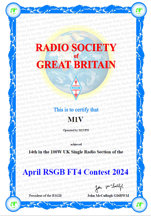
14th (51) - UK 100w Restricted - (286 Series points)
Single Operator, All Bands - 100w (85w)
61 QSO - 1,170 points
Contest Notes: Good activity, but was hard going at times. Good multipliers but lower QSO numbers than other sessions.
Yaesu FT-2000, 80m FD4 OCFD Antenna at 12m, Palstar AT-2K Tuner and G4ZLP Interface.
🏆 BARTG RTTY 75 Sprint Contest - (April 2024)
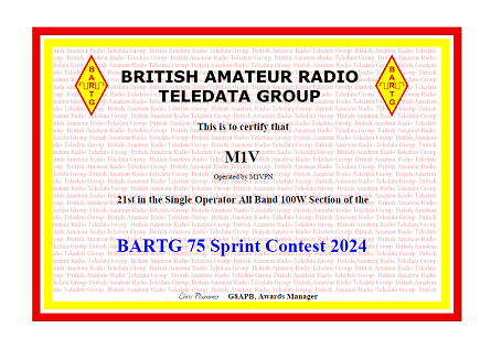
4th (11) England, 21st (53) DX,
Single Operator, All Bands - 100w (85w)
108 QSO - 2,160 points
Contest Notes: A new contest for me, as I had always missed this one. A small configuration change in the MMTTY and 2Tone setup, and GRITTY does not support the 75 Baud rate so was down to two decoders. A fairly slow contest, and heard a couple of US stations but they disappeared before I could call them back, so just the EU stations and not many multipliers either so not going to score well in this contest, but it wasn't very different than usual RTTY contesting.
SO2V - Yaesu FT-2000, 80m FD4 OCFD Antenna at 12m, Palstar AT-2K Tuner and G4ZLP Interface. (SignalinkUSB for SO2V Audio)
🏆 PACCDigi Contest - (April 2024)

2nd (2) England, 22nd (33) DX,
Single Operator, All Bands - 100w (85w)
93 QSO - 2,448 points - 6.5 hrs
Contest Notes: Due to solar conditions, the bands were awful for this contest, with very low rates achieved. Whilst I set out to be in this contest all day, after two hours I went off out into the garden due to the lack of stations heard. I periodically ran a few times but nothing much came to the call. Some increase in stations at the end. I did think about moving over to the RTTY and FTx mixed category, but decided to carry on with RTTY Only, and did try out various SO2V operating procedures and refined my custom keyboard shortcut options. First time entering this contest, but will try to do this again next year, with hopefully better conditions !
Well, I entered the wrong section, and not the RTTY one so had a poor placing. If I had entered the RTTY as planned, I would have been 3rd ! Oooops !
SO2V - Yaesu FT-2000, 80m FD4 OCFD Antenna at 12m, Palstar AT-2K Tuner and G4ZLP Interface. (SignalinkUSB for SO2V Audio)
🏆 EA RTTY Contest - (April 2024)

2nd (11) England, 15th (375) DX,
Single Operator, All Bands - 100w
429 QSO - 112,833 points
Contest Notes: Bands were very noisy and didn't really recover all contest. Some busy periods with some long slow periods too, but the DX was there too if you could find them, Mostly by accident at this station ! Multipliers started slowly too, but soon started to increase. DX into Indonesia, US, Canada, St Helena, Namibia. Couldn't get a good Run in this contest, and some fairly robust jumping on Run Freqs from HP stations too. First time I've been keyed over to make me move as well (Spoiler, didn't work).
More SO2V operating, but using VFO B for S+P as duelling CQ's didn't return much increase in rate vs effort. Keys now selected for the keypad now as I identified the shortcuts most used in this contest as the ones to try first. A couple of them will need some delay times added (The FT-2000 when switching VFO's, and with both on the Internal ATU, needs 2 seconds else the radio TX's, but the CPU locks it out. MMTTY thinks it is transmitting and it all falls over in a heap !)
SO2V - Yaesu FT-2000, 80m FD4 OCFD Antenna at 12m, Palstar AT-2K Tuner and G4ZLP Interface. (SignalinkUSB for SO2V Audio)
🏆 CQ WW WPX Phone Contest - (March 2024)


18th (128) England, 302nd (1575) Europe, 586th (3367) World. - 6th in Classic.
Single Operator, All Bands - 100w
341 QSO - 161,694 points
Contest Notes: Although I intended to enter this contest for the Classic and the full SOAB LP section, but a migraine decided to affect my operating, so only 14 hours mostly at the evening sessions. Some good DX into China, US and Caribbean, with some new WPX entities for the log. Disappointed to not enter this properly, but these things happen. Station worked well, as expected but as the reduced operating time meant that I only worked 3 bands. Only operated SO1V, as I'm not setup for SSB SO2V just yet and only used the OCFD, the 6BTV wasn't giving anything extra and there was no need to use the Bevflex-4.
Not expecting to place well in this contest but did enjoy the operating time that I did have !
Yaesu FT-2000, 80m FD4 OCFD Antenna at 12m, Palstar AT-2K Tuner.
🏆 RSGB FT4 Series - Contest 2 - (18th March 2024)
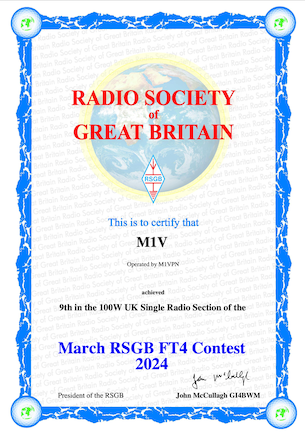
9th (51) - UK 100w Restricted - (364 Series points)
100w Single Operator, Low Power, All Bands - 85w output
60 QSO's, 1,860 Points
Golden Log
Contest Notes: This sprint contest is an interesting one, as this session saw my station back to having the OCFD available, and a noted increase in DX stations on the bands for the contest. After an initial flurry of activity, things slow up about an hour in, and I need to find the answer to having a better run, or S+P session. With a 90 min session, and QSO's taking 60 sec (4 x 15 sec), finding 90 QSO's with one VFO is pretty much all I can do, but I'm currently 30 short ! Fun session though, for something different.
Yaesu FT-2000, 80m FD4 OCFD Antenna at 12m, Palstar AT-2K Tuner and G4ZLP Interface.
🏆 BARTG HF RTTY Contest - (March 2024)
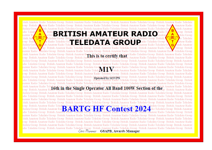
16th (349) World, 15th (231) Europe, 2nd (23) England
Single Operator, All Bands - 100w (SOAB100)
602 QSO - 603,576 points (4 Dupes)
Contest Notes: The second session with SO2V configured, and although with the band change timer, this means that it's Run and S+P in the same band, but that brought a good increase in QSO totals, that I would not have got without the second VFO. The shortcomings of SO2V, with loss of audio on TX can be managed, but shows what more can be done with SO2R.
Good session, and managed time around at home commitments, with a later start but think I managed the time well considering that. Station worked well again, but SO2V brings with it a larger mental load, therefore was tired after ! I have identified a number of operating improvements, which is to be expected being new to this style, and have some equipment identified.
SO2V - Yaesu FT-2000, 80m FD4 OCFD Antenna at 12m, Palstar AT-2K Tuner and G4ZLP Interface. (SignalinkUSB for SO2V Audio)
🏆 EAPSK63 Contest - (March 2024)

1st (10) England, 8th (212) DX,
Single Operator, All Bands - 50w
393 QSO - 98,835 points
SO2V - Yaesu FT-2000, 80m FD4 OCFD Antenna at 12m, Palstar AT-2K Tuner and G4ZLP Interface. (SignalinkUSB for SO2V Audio)
🏆 RSGB FT4 Series - Contest 1 - (26th February 2024)
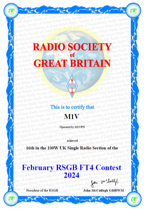
16th (60) - UK 100w Restricted - (262 Series points)
Single Operator, Low Power, All Bands - (Antenna was Hustler 6-BTV due to OCFD being down for Storm)
56 QSO's, 900 Points
Golden Log
Yaesu FT-2000, Hustler 6-BTV, Palstar AT-2K Tuner and G4ZLP Interface.
🏆 CQ WPX RTTY Contest - (February 2024)


1st (46) England, 35th (742) Europe, 55th (1363) World.
Classic 1st (10) England, 4th () Europe, 8th () World.
Single Operator, Low Power, All Bands
829 QSO's
Yaesu FT-2000, 80m FD4 OCFD Antenna at 12m, Palstar AT-2K Tuner and G4ZLP Interface.
🏆 BARTG Sprint Contest - (January 2024)
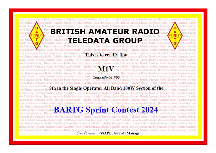
4th (24) England, 8th (349) World.
Single Operator, Low Power (SOAB100)
535 QSO's, 136,425 Points
🏆 ARRL RTTY Round Up Contest - (January 2024)

2nd (15) England, 11th (257) Europe, 18th (375) World.
Single Operator, Low Power + Limited Antenna Overlay (Single wire, under 50ft AGL)
444 QSO's, 33,300 Points
🏆 SARTG New Year Contest (Jan 2024)
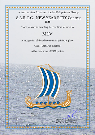
1st (9) England, 37th (119) DX
Single Operator, All Bands, One Radio
69 QSO's, 2277 Points
🏆 CQ WW DX SSB Contest (Oct 2023)


5th (109) England, 68th (1211) Europe, 137th (2400) World
Classic - 2nd (55) England, 27th (469) Europe, 47th (871) World.
Single Operator, All Bands, Low Power + Classic
832 QSO's, 292,672 points - ( 34.5 hrs)
🏆 PL259 Makrothon RTTY (Oct 2023)

6th (24) England, 108th Europe, 157th (435) World
Single Operator, All Bands, Low Power
Note: Entered to test new N1MM+ set-up, and was only on-air for under half (7.5hrs) of the contest.
194 QSO's, 579,500 points
Golden Log
🏆 BARTG Championship 2023 (All BARTG 2023 HF Contests)
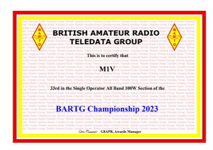
33rd Place (564), 2nd England (48) - SOAB 100.
Note : I used my personal call-sign for two contests, and M1V for the last sprint. Combining both callsigns would have placed 30th, however M1VPN was placed 85th, and M1V 33rd.
🏆 CQ WW RTTY (Sep 2023)

2nd (27) England, 41st Europe (472), 72nd (906) World
(Classic - 1st (19) England, 18th (174) Europe, 29th (333) World)
Single Operator, All Bands, Low Power + Classic Low Power
🏆 BARTG PSK63 Sprint (Sep 2023)
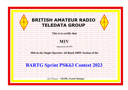
1st (9) England, 10th (44) Overall
Single Operator, All Bands, Low Power - SOAB100
85 QSO, 3230 points - (Golden Log)
🏆 SARTG WW RTTY Contest (Aug 2023)
19th (296) Overall - 2nd (9) England.
Single Operator, All Bands, Low Power
350 QSO - 464,380 pts
🏆 CQ WW VHF (July 2023)
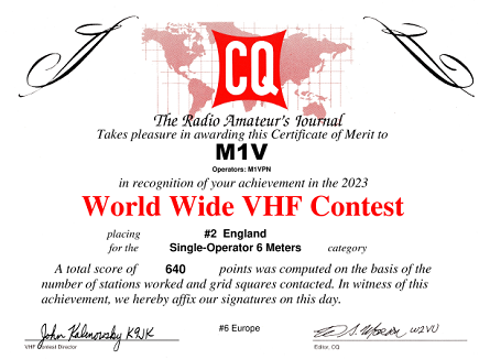
2nd (2) England, 5th (28) Europe, 25th (266) World.
Single Operator, 6m Band Only
32 QSO - 640 pts - 20 Grids
🏆 EARTTY Contest (April 2023)

34th (440) DX, 3rd (18) England
Single Operator, All Bands Low Power
275 QSO - 58,519 pts, 50 EAP / 86 DXC
🏆 CQ WW WPX Phone (March 2023)


8th (111) England, (3rd )(26) Classic) 97th (1346) in Europe, 222th (3009) in World.
Single Operator, All Bands Low Power
545 QSO (1 Dupe) - 285,572 pts, 329 WPX
🏆 BARTG HF RTTY Contest (March 2023)
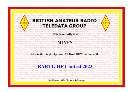
73rd (340) World, 6th (15) England
Single Operator, All Bands (SOAB100)
372 QSO - 150,288 pts
🏆 EAPSK63 Contest (March 2023)

37th (256) DX, 6th (17) England.
Single Operator, All Bands (50w Max Power)
258 QSO (1 Dupe) - 50,184 pts, 47 DXCC, 52 EAP
🏆 BARTG RTTY Sprint (January 2023)
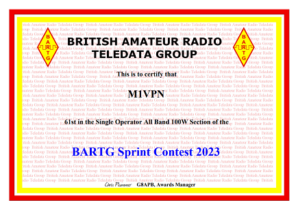
61st (356) World, 9th (35) England
Single Operator, All Bands 100Watts (SOAB100)
279 QSO, 48 Mults,
40,176 Points
🏆 ARRL RTTY Round Up Contest - (January 2023)
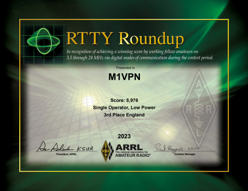
3rd (14) England, 63rd (212) Europe, 79th (301) in all DX
Single Operator, Low Power Unassisted
198 QSO's, 48 Multipliers
9,504 Points
🏆 SARTG New Year RTTY Contest - 2022 (1st January 2023) 🏆

28th (121) World, 1st (6) England
53 QSO (45x40m, 8x80m) 1166 Points
Single Operator, All Bands, Low Power.
🏆 BARTG Championship 2022 (From all BARTG HF Contests 2022)
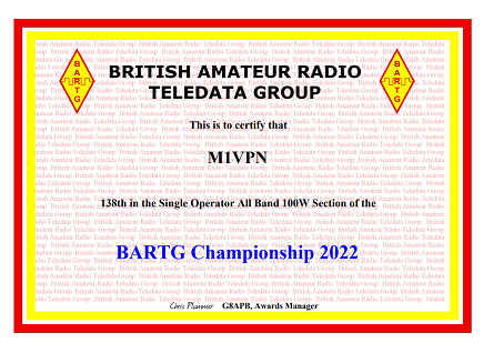
138th (718) SOAB100, 13th England
🏆 ARRL 10m Contest - Phone (December 2022)
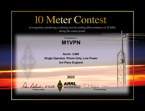
3rd (11) England, 374th (986) DX
Single Operator, Low Power Unassisted
65 QSO's, 31 Multipliers
3,968 Points
🏆 DARC Worked All Europe RTTY Contest - (November 2022)

5th (23) England, 239th (627) Europe.
Single Operator, All Bands, Low Power Unassisted (10h 35m)
208 QSO's - No QTC.
46,384 Points
🏆 CQ WW DX Contest - (October 2022)


Single Operator, All Bands, Low Power Unassisted + Classic Overlay (33h 17m)
668 QSO's
Score 218,940 Points
5th England / 4th Classic (85), 62nd Europe (1019), 143rd World (2242).
🏆 CQ WW RTTY Contest - (Sept 2022)


10th England / 2nd Classic (30), 78th Europe (432), 133rd World (877).
Single Operator, All Bands, Low Power Unassisted + Classic Overlay (19h 34m)
462 QSO's
Score 176,675 Points
🏆 CQ WW VHF Contest - (July 2022)
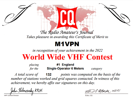
First (2) - England, 26th (40) Europe, 242nd (349) World
Single Operator, 6M Band Only, Low Power, Non-Assisted.
12 QSO's - Score : 132 Points
🏆 BARTG HF RTTY Contest (March 2022)
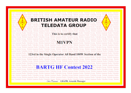
123rd (out of 327 in Section) - 16th in England
Single Operator, All Bands, 100w (running 50w)
198 QSO's, 64 DXCC, 5 Cont,
Score : 75,240 Points
🏆 EAPSK63 Contest (March 2022)

Single Operator, All Bands (50w Max Power)
184 QSO's, 47 DXCC, 58 EAP
Score 38,640 Points
Results - 16th World, 4th England - Score 36,668 Points
🏆 CQ WPX RTTY Contest (Feb 2022)
Single Operator, All Bands, Low Power + Classic Overlay (12h 27m Only)
296 (307) QSO's, 219 (223) WPX
Score (claimed - 208,505) 190,092 Points
11th UK, 253th Europe, 402rd World
4th in UK Classic Overlay


🏆 BARTG RTTY Sprint (January 2022)
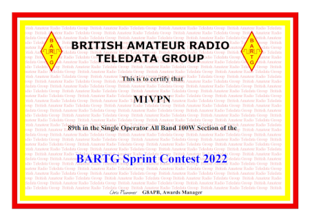
89th Place (out of 550)
Single Operator, All Bands, 100w (running 50w)
284 QSO's, 40 DXCC, 4 Cont,
Score : Claimed 47,712 Points, Confirmed 47,040 Points. (Error rate 0.7%)
🏆 SARTG New Year RTTY Contest - 2022 (1st January 2022)
53rd Place (out of 139) - 4th in England.
52 QSO (8x40m, 18x80m Multipliers) 1352 Points
Single Operator, All Bands, Low Power.
🏆 CQ WW DX Contest - 2021 (October 2021)

Single Operator, All Bands, Low Power + Classic Overlay
616 QSO's, 40 Zones, 159 DXCC - 136,912 Points
5th (100) UK, 114th (1190) in Europe, 218th (2433) World
6th in Classic Overlay
🏆 UKEICC DX Contest 2021

Golden Log ! - No Deductions
56th Place Overall, 28th in Unassisted (all), 26th in UKEI, 19th in Low Power (all)
7th in Low Power, 12hr Section (all) - 5th in UKEI
Single Operator, All Bands, Low Power. 12 Hour Section.
174 QSO's - 60 DXCC, 43 Districts
DL DX RTTY Contest 2021
Awaiting Results
Single Operator, All Bands, - 6 Hour, Dipole.
135 QSO's, 78,192 Points / 50 DXCC
🏆 Ukrainian DX Classic RTTY Contest 2021 (Single Operator-All Bands-6 Hours-RTTY)
33rd - World, 4th - England
97 QSO's Recorded, 87 QSO's Scored
292 Points, 47 Multipliers. 13724 Total Points (89,7% Log Accuracy)
Single Operator, All Bands - 6 Hour
102 QSO's, 9,593 points / 37 DXCC, 16 Oblast.
🏆 EU PSK DX Contest - 2021
SO HP EU- 21st (2nd England)
Final Score - 43788 Points
133 QSO, 53 DXCC, 111 EU Call. Confirmed.
Single Op, High Power, All Bands
🏆 CQ WPX Contest SSB - 2021


5th in England (out of 106), (2nd out of 25, in England for Classic Overlay) Single Operator, All Bands, Low Power (Classic)
100th in Europe (out of 1343), 143rd in World (out of 2720).
585 QSO's, 360 WPX - Overall Error Rate - 3.0% (3.6%)
🏆 BARTG HF RTTY Contest - 2021
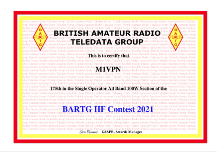
150 QSO's - 16,200 Points - 175th / 332 in SOAB 100w Section
🏆 UBA PFX PSK63 Contest - 2021

🏆 UKEICC DX Contest 2020

Final Score - 50th Overall, 18th in Low Power, 24th in UK/EI Section
129 QSO's - 37 DXCC, 43 Districts
🏆 CQ WW DX Contest - 2020

18th in England, 308th in Europe, 504th in World (Single Op, Low Power, All Bands Unassisted)
405 QSO's, 110 DXCC - Overall Error Rate - 1.4% (2.7%)
The OCFD antenna has worked well, and I've even tuned it on 160m, but the model and the resulting FT8 QSO's are directly related. It's known as a Skywarmer, and therefore the NVIS radiation means 1500 miles max, so I had to look at what I could do. There is no room where I could make a full 160m OCFD, but on the short leg, I do have a few metres to play with so looked at what I could find.
The outcome is the data at www.qsl.net/df1hf/OCF_160m.htm and the work done by DF1HF.
It all looks very simple, with a 50mm PVC pipe, 125 turns and pop that on the short end, with a 4-5m tail. This set of dimensions need to be changed as I have 55mm pipe in stock after a Screwfix mix-up when building the QFH NOAA Antenna.
The translated values for 55mm is 115 turns, so that will result in about 20m of cable needed, plus the 4-5m tail.
The result will replace the wire to dacron cable insulator, pass the dacron through the coil and run the tail along and down the tree if needed.
The resulting MMANA GAL model
The antenna analyser sweep
When starting with the AEA PK-232, there are a few commands that may come in useful especially in the pursuit of an HF Packet Station. The first is the default configuration, which I paste into my PuTTY Command line once I've made contact with the PK-232 via Serial. This may be useful for you, or you may decide the options are different ;
mycall <CALLSIGN>
VHF off
HBAUD 300
EXPERT ON
packet
daytime YYMMDDHHMMSS
BTEXT <CALLSIGN>, <CALLSIGN>-1 MBX [LOC]
CText Welcome to <CALLSIGN>PK-232, I'm not here right now, Please leave a message on <CALLSIGN>-1 Maildrop.
Mtext Welcome to <CALLSIGN>-1, PK-232MBX Maildrop
BEACON EVERY 90
mymail <CALLSIGN>-1
passall on
8Bitconv on
constamp on
mdigi on
mproto on
mstamp on
xflow off
maildrop on
mdmon on
mon 6
MAXFRAME 1
PACLEN 60
DWAIT 0
wide off
Packet Commands
MailBox
Is the STA LED FLASHING ? Check MailBox Server, you have a message.
cmd:mdcheck
You have mail.
List Messages
(AEA PK-232M) 18396 free (B,E,K,L,R,S) >
l
Msg# Size To From @ BBS Date Time Title
3 PN 84 <CALL><CALL>04-Jul-20 14:14 test from portable station
Read Message
(AEA PK-232M) 18396 free (B,E,K,L,R,S) >
READ 3
Msg# Size To From @ BBS Date Time Title
3 PN 84 <CALL><CALL>04-Jul-20 14:14 test from portable station
test message into MBX for <CALL>-1, TEST TEST TEST
/E
Delete Message
(AEA PK-232M) 18396 free (B,E,K,L,R,S) >
k 3
*** Done.
(AEA PK-232M) 18536 free (B,E,K,L,R,S) >
cmd:
Create or Leave a message
cmd:mdcheck
(AEA PK-232M) 18396 free (B,E,K,L,R,S) >
s ALL
Subject:
Welcome to <CALL>
Enter message, ^Z (CTRL-Z) or /EX to end
<MESSAGE FOR ALL TO RECEIVE>
/EX
Message stored as # 1
(AEA PK-232M) 18172 free (B,E,K,L,R,S) >
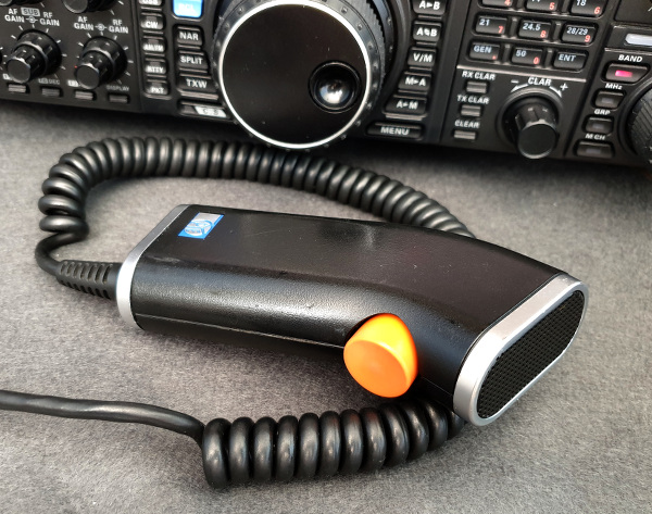
The Pye Shaver Mic, there's something about the form. Is it the reminder of the 1970's Professionals TV series (Ok, that was the PocketFone 8 but looks similar), or the fact that it looks like nothing else in the Radio world ? I don't know but when I saw such a thing exists I knew I wanted to have one as a functional microphone in my shack. Formerly made for Pye PMR sets, the configuration of the mic does not lend itself to the modern Yaesu, so some degree of engineering needed to be done but the aim was to re-use as much of the microphone as possible whilst making it a good FM Repeater Mic, maybe going further with some audio filtering to give SSB tailored audio too. Let's see how far it goes, but this has plenty of scope for expansion !
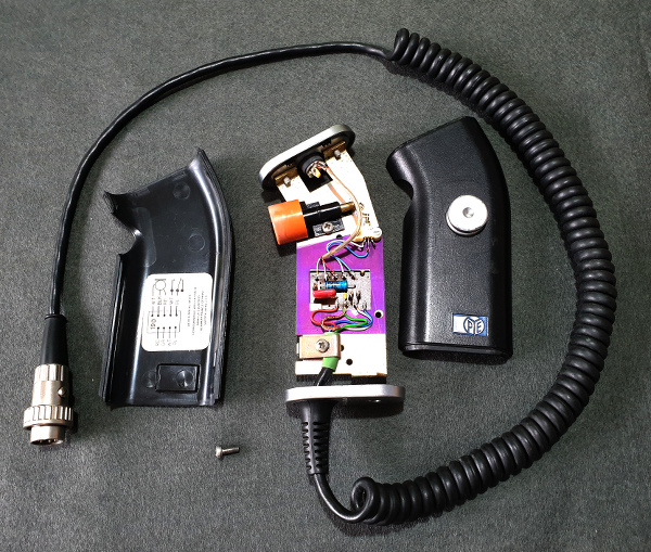
Fig. 1 Opened Pye Shaver Microphone
The Microphone
Purchased on Ebay for £15, it was in nice condition, 6/10 with lots of glue residue and well used plastic shell. The Orange button had faded to a lighter orange but the microphone grill was 9/10 and internally as new. Internally, the quality and feel is excellent as would be expected for an AM PMR in the 70's. Good gauge metal frame and well engineered PTT, switching and PCB mount. The Mic mount in rubber was in good condition too, holding a 10v, 10mm insert. 4 wire + shield curly cable terminating in a lock connector.
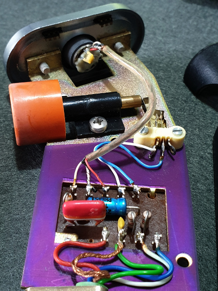
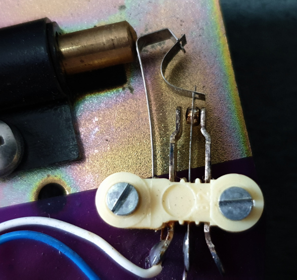
Fig. 2 & 3 Internal Pye Shaver Microphone highlights (PTT and PCB)
The Plan
Create a Electret, Powered Microphone for connection to a Yaesu Radio, taking inspiration from the MH-31 Modifications by M0UKD / M0GEO and other advice from across the internet on the use of Electret inserts. Main requirements are for good FM audio input, some filtering via passive components, and correct output level into the Mic stage of the radio (FT-847)
The Parts
Choosing an Electret insert sounds easier than it actually is. Do you go for a 50p, Cheap insert with no datasheet, or look at the Panasonic WM-range for a few Pounds. Based on the Buy Cheap, Buy twice principle the Panasonic route looked better. Now, Which one ? WM-3x, 5x or 6x ? Piling through the datasheets for these discontinued items it looked like the WM-62 was the most used in pro audio, and also had a good up to 10v performance. It was only 6mm though and the original mic holder was 9-10mm diameter. The WM-52 looked like it covered almost all the requirements, but then I could not source easily. The WM-54B was sourced, being the WM-52A with the legs soldered on. Whilst I didn't need the legs, the would help with the soldering if nothing else.
Oddly, I didn't have an 8.2k Ohm resistor, so a 10k and 47k in parallel made a good substitute.
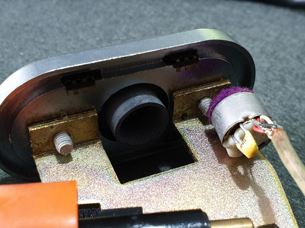
Fig.4 Pye Shaver Microphone bay (with microphone element removed)
The Circuit
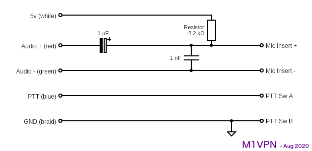
The circuit, based on the M0UKD MH-31 modification, the Panasonic WM-54B was connected as per the following diagram. The aim was to try to re-use the Pye PCB that is internal to the microphone, either by replacing the components and/or re routing tracks. Whilst I tried to realign the original PCB, it was such a lot of re-engineering and long traces that I thought that RF would become an issue, so the PCB was replaced with some strip board, cut to size and drilled to fit into the space.
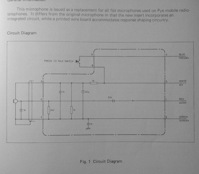
Fig. 5 Original Circuit Diagram for the Shaver Mic (From Pye Manual)
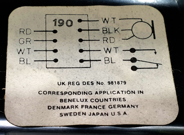
Fig. 6 Original Circuit Diagram inside the Shaver Mic.
| Wire Colour | Old Function | New Function | Yaesu Pin |
| White | 10v | 5v | 2 |
| Red | Audio + | Audio + | 8 |
| Blue | PTT | PTT | 6 |
| Green | GND | Audio - | 7 |
| Shield | GND | GND | 5 |
For PTT, the switch will now switch Pin 6 to ground pin 5, so the PCB trace will be cut and jumpered to GND.
The audio signal now will be passed out of Pin 8, (Mic +) and Pin 7, (Mic -) but will have a drop resistor for the incoming 5v, and a DC block capacitor.
The Circuit
The 8.2k Ohm resistor works in series as a voltage divider with the internal 2.2k Ohm resistance of the Insert, delivering 1v into the microphone element. The 1 uF capacitor filters the DC component and passes the audio signal into the radio via the curly lead.
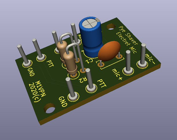
The Finished PCB and Internal Wiring
The final PCB is here, where the circuit providing the Microphone supporting components and cross connection to the curly lead meet.
*** PCB Pic
This is a tidy install inside the microphone, and apart from the Yaesu 8-pin, there are no signs it's been converted into something else which was the plan. I suppose I could lay out a purpose built PCB for this, but the prices and numbers when I'd want 3 PCB's max seemed beyond reasonable. Strip board will do for now, and it's working. I've got the Gerber's if I change my mind though, or I have another PCB order going out.
Clean-up
I wanted to clean up the Orange PTT, it had broken down due to Sunlight, so I used the 3 grades of Novus Plastic Polish both manually and using a dremel mop. It cleaned up ok, but may keep an eye on getting another mic in better shape on Ebay in the future.
On-air Performance
In the excitement (No, I don't get out much) after metering out the circuit with the multimeter to check for shorts, dodgy soldering and stray wires, all was found to be good, and stable.
I then plugged in the microphone to the FT-847 for a few calls, with monitor switched on. First call into EA8DHV resulted in a good steady 59 signal, and no repeats. Second call into LZ1UBO resulted in a good QSO with unsolicited "Broadcast Audio" report. The Monitor audio from the radio also sounded a good audio signal was being sent into the radio, but listening to yourself is always difficult. I'll organise some recording on my SDR, to see what it does sound like.
The Yaesu FT-847 Mic Gain is now only on 10 o'clock, which is low for any of the other microphones I've got such as the MD200-A8X which needs full Mic gain. On the Yaesu FT-2000, Mic gain is only on 10, but sounds good without going into setting up the processor.
The End
This is a pleasing result to a bit of a crazy idea, but an enjoyable project and an excuse to get the soldering iron out !
Now, what next because I have a spare insert...
Thanks to M0UKD for the initial circuit and work and M1GEO for his write-up of his Yaesu modification.
