Uncategorised
Where
20m - 14.105.000 Mhz
Lower Side Band - LSB
Depending on the device you use, this CF will differ. On a PK-232 TNC, this will be 14.105.510 Mhz because of the tones. You will see the waterfall on Soundmodem so can select the stream. I'll expand on this further down this page.
14.105.000 Mhz
- PK-232 (US) [2110/2310] = 14.105.510 Mhz
- Kantronics KAM [1600/1800] = 14.105.000 Mhz
- UZ7HO Soundmodem - Tune using Waterfall Beacons.
Who
Anyone with a HF transceiver or Receiver and a 20m Antenna, TNC or Soundcard and a PC.
Why
The technology before the internet and these days often seen as a novelty. It would be a shame to loose the skills in Packet radio, especially the HF DX Packet communications. TNC Equipment is cheap on Ebay or using a soundmodem is just a matter of the right cable for your PC to Radio.
What
Have a listen for the beacon calls, you should set these to 900 seconds maximum and then call back, either to the call or to the mailbox ID. Leave Messages or try to digipeat to another station beyond your reach ? All fun things to try on a Sunday morning in the shack.
How
http://www.vectorbd.com/bfd/packet/hfpacket.txt
UZ7HO Soundmodem
http://uz7.ho.ua/packetradio.htm
https://www.youtube.com/watch?v=q9evYp6HcdA
http://rickmega.com/NBEMS/UZ7HO_Setup.pdf
TNC
Project in Progress ....... -.-. --.- -.-. --.-
Receiving the NOAA Weather Satellites is a fairly easy project to complete, and with the use of an SDR, Cheap or moderately expensive the pictures can be received and saved away, displayed on a website or just to take a quick look at.
The main components needed will be no surprise ;
- Antenna - A QFH or Quadrifilar Helix Antenna made from a Coax off-cut
- Low Noise Amplifier and accessories - NooElec Sawbird + NOAA, 5v Bias Tee and DC Blocker.
- Receiver - ADALM Pluto SDR
Quadrafilar Helix Antenna
The antenna was built using a number of instruction pages on the internet as none of them actually demonstrated the Coax QFH right through to the end. Some of my measurements were abitrary and also due to a materials supply issue (Screwfix sold me a 55mm Pipe and not a 50mm as ordered and I didn't notice till I'd cut it up.) I had to deviate somewhat.
General Construction
The principals are for a QFH to receive APT Weather pictures you need a RHCP (Right Hand, Circular Polarised) antenna. Yes, an Omni Vertical will pick up the signal somewhat, but not at a level where you can raster the images. This does look time consuming or difficult but it's not when you get started. In the case of the antenna I built, it took an afternoon.
Mine is built to this specification, partially - https://www.instructables.com/NOAA-Satellite-Signals-with-a-PVC-QFH-Antenna-and-
The key aspects of this is to measure the hole placement, then measure them again. Then measure them again. What I found was when using the http://jcoppens.com/ant/qfh/calc.en.php calculator, the above design needs some adjustment. Remember, you are using a Coax QFH, not a Copper one so some measurements change. Anyway, the wiring diagram is correct and therefore it is performant. I did sweep it with my antenna analyser, which confirmed it was a near match. As we're not transmitting, this isn't needed.
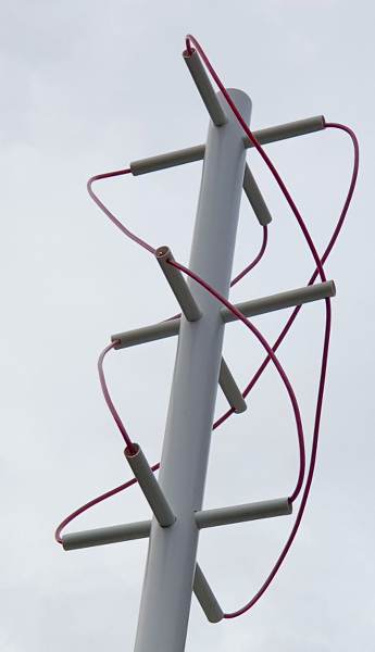
Coax QFH Antenna (22mm Conduit into 55mm PVC Waste pipe)
Low Noise Amplifier
Installation of the will assist in picking up the low horizon signals, and with the SAW filter in this particular device, helps with string adjacent signals from other sources like FM Broadcast which is near by. The device chosen here is the NooElec Sawbird + NOAA which is a Bias Tee powered filtered Pre-Amplifier which can be mast head mounted. I wanted to mount this inside the antenna, but could not easily connect it so have placed inside a mast mounted box. The Coax I used was also too big for an SMA fitting, so is terminated in BNC, then converted to SMA inside to the Pre-Amp.
The Bias T and 5v Supply are Generic Ebay Items. The Pluto also requires a DC Block on the input. It will go into protection mode without it.
Receiver
The ADALM Pluto SDR is more expensive than your RTL dongles, about £100 more but you do get transmit capability and opensource firmware, Access to a FPGA and embedded linux for projects too. The down side for experimentation, its an expensive device when you stick too much DC in the front end and kill the device. Luckily it has some good protection circuits, which have been well tested by me with various school boy errors (My defence is that I only have a degree in SatComms and that was 25 years ago, and I didn't kill the HP Spectrum Analyser in the lab with DC back then either)
Using SDR Console, this software enables complete control of the receiver and what we need to do for receiving a signal. There are others, like SDR# and SDR Angel but I've used HRD Deluxe for years, which Simon originally wrote (Fact: I still use his last version, because I like it better than the recent releases)
Virtual Patch Cable - This takes the Audio out from the SDR and allows it to be piped back into another application, which is WXtoIMG...
WXtoIMG Reloaded - This software does the heavy lifting, where it can show the schedules of the passes and receives, renders and organises the images. It also places them into a webpage for external viewing.
Capturing other things
Building all this kit, and a dedicated machine to capture these images is fine, but what else can it do ? well, the other part of SDR Console which deals with Satellites will allow all manner of capabilites that are really useful like sorting Doppler Shift and tracking passes but it also allows scheduling and controlling the SDR. This means the operation of moving between the 3 NOAA satellites is automated. It also means other satellites that are passing, like the ISS can also be received. Now, whilst the ISS does not transmit with RHCP, it instead uses a vertically polarised antenna, the losses are not so much that any of the SSTV pictures which are occasionally transmitted are not able to be captured.
Cables and connectors for connection between the PK-232 / PK-900 TNC and Yaesu FT-847 for HF / VHF
There are a few issues to be aware of. In the case of using the Data port in the FT-847, there is a hang time on the PTT that is too long for Packet QSO's to be viable. I posted a message in the Packet Radio Forum that I belong to and another user of the FT-847 had the same issues and resorted to the Front Mic Connector, and rear Ext Speaker for the connection. That started to look a bit of a cable nightmare when dealing with all the other cables I have here. I had a bit of a google around and fell upon a note in a SuperControl.de page about long changeover on the FT-847 and there was another way.
The note said that some people had good results with using a 100nF (0.1uF) capacitor or 200nF (0.2 uF), so I set about trimming off all the nice neat heatshrink that I'd put on when making the cable up. Replacement of the capacitor for a 100nF has speeded up the transfer to one that will now support AX-25 Packet.
Anyway, I learned so you don't have to. You can either build the cable as I have below or experiment with a different capacitor value. There are also notes elsewhere that say to up the resistor to a 2.7k Ohm one but there is little explanation of why.
FT-847 Data Connector for HF Digital Modes
The FT-847 uses a 3.5mm stereo jack for HF digital signals, and therefore is fairly easy to connect to a TNC. The difficulty with the PK-232 is the lack of TNC connectors, if you are not lucky to get cables with your TNC. I didn't with any of my TNC purchases, so looked around in the supplies boxes and USB 5-pin Motherboard headers work just fine. These are wired to a small piece of strip board to populate the Capacitor/Resistor circuit to provide PTT, as designated by the Yaesu Radio User Manual.
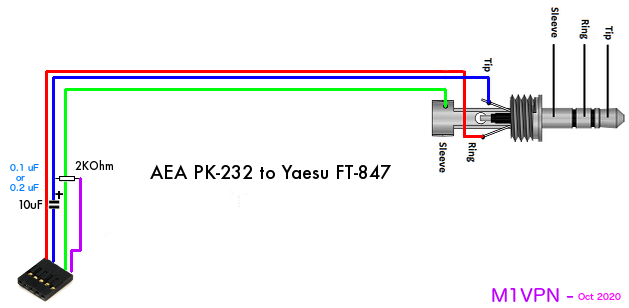
The cables need to be at least shielded and wired to provide good ground connections between the TNC and Radio, else ground loops will give poor signals, transmit and receive. I have used JY-8022 Audio Cable (Twin shielded cable, in 8-form), Neutrik 3.5mm Jack and a homebrew TNC connector.
Parts
JY-8022 Twin Audio Shielded Cable
2k Ohm 1/4 watt Resistor
10 uF Electrolytic Capacitor - SEE ABOVE NOTE FIRST
5 pin Female Dupont Connector
REAN Stereo NYS231BG-LL Extra large entry 3.5mm Mini Jack plug
Assembly
Connect as diagram with 3.5mm Jack TRS ;
Tip - Signal T
Ring - Signal R
Sleeve - Ground
Connect Veroboard as circuit diagram ;
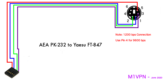
PK-232 TNC connector ;
Pin 1 - RX Audio = Signal R
Pin 2 - TX Audio = Signal T
Pin 3 - N/C
Pin 4 - Gnd = Ground
Pin 5 - PTT = Via Veroboard circuit
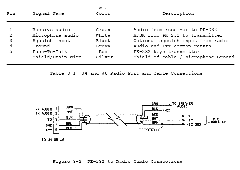
AEA pin-out for PK-232
FT-847 Data Connector for VHF Digital Modes
The Yaesu FT-847 has two connections for data modes, one for HF data and one for VHF/FM Packet. I detail the HF Data connector to the Pakratt 232 TNC on another page, and this page concerns the VHF/FM connector. This is a 6 pin DIN presentation, in a very small DIN configuration.
This connector, as you can see from the Yaesu diagram below has two speeds, 1200 and 9600 bps. This is indicated on the diagram for the cable ;
Wiring diagram
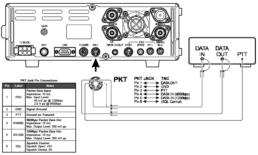
Yaesu Manual Pin-out for PKT port on FT-847
FT-847 Data Connector for HF Digital Modes on PK-900
Parts
JY-1199 4 core shielded audio cable
5 pin Female Dupont Connector
5 pin Mini-DIN Connector
Assembly
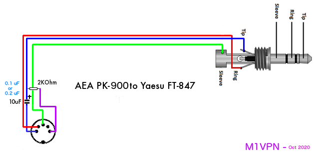
Wire as circuit diagram, ensure shield provides continuity between Gnd and 5 pin Mini-DIN Connector to prevent ground loops and hum.
After the PK-232, I wanted a PK-900 but AEA PK-900 is a rare sight. I found one on E-Bay with only 6 mins left to go. I promptly bid and won so now have one of the best TNC devices made. The connection cable below is for the HF Data port on the FT-847 to the PK-900 using the same cables as for the other PK-232 cables on this site.
Parts
REAN Stereo NYS231BG-LL Extra large entry 3.5mm Mini Jack plug
JY-8022 Twin Audio Shielded Cable
2k Ohm 1/4 watt Resistor
10 uF Electrolytic Capacitor - SEE ABOVE NOTE FIRST
5 pin DIN Connector
Wiring Diagram
Having an MD-200A8X, I rarely need to look at other audio sources. Combined with the majority of radio time these days being on digital modes, I have not had the need to buy additional kit, until now.
Like most of the planet, 2020 didn't really go to plan and I was working from home and replacing endless video conferences and meetings in the office with Microsoft Teams and Amazon Chime calls. Quite frankly the audio on these calls is awful, with a mixture of cheap tinny mic's in laptops and the odd cheap, or sometimes expensive headset that doesn't really represent the voice of the person very well, and being USB isn't terribly useful for anything else. The additional fact that any reasonably priced headset has long gone and is on back order, I thought I'd have something I can use on the radio when I'm back at the office, instead of getting lost in a box somewhere.
I didn't find a cable diagram for a Yaesu 8-pin to XLR cable so have put the following information together in the hope it helps someone else get their BPHS-1 on the air a bit quicker than I did.
I've also added all the homebrew cables I make for my outboard audio connections.
(Yaesu 8-pin) > (XLR) for Headset Direct
(Mixer) > (Attenuator) > (Yaesu) for Xenyx Mixer into Radio.
(XLR) > (Isolator) > (Attenuator) > (Yaesu RCA) for audio isolated connection from Behringer Mixer to Radio.
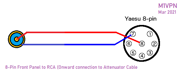
(Yaesu 8-pin) > (RCA Socket) Breakout cable for front mic socket for cable above.
Audio-Technica BPHS-1 direct to Front panel Yaesu 8-pin
The following cable is a alternative to the Heil CC1-XLR-Y8BAL cable, without the PTT in this case, but can be easily added. I've not seen one of these cables to comment on the build quality or anything within the wiring that may be better or worse ? This one works well though, and costs about £5 + your time.
Yaesu 8-pin to XLR
- Neutrik XLR Female Connector
- Yaesu 8-pin Connector
- 2 core plus shield cable
- Heat shrink (preferably not red, it's all I had in that size that was accessible)
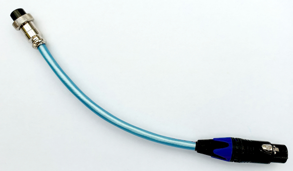
Yaesu 8-pin end connections
Pin 8 - Signal +
Pin 7 - Signal -
Route shield to the plug casing by clamping the shield back through the connector. Test for continuity whilst mobilising the cable to ensure good contact.
PTT can be added by placing a switch, or two pole connector between pins 6 (ptt) and 5 (gnd). There have been reports that this can lead to RF breaking into the cable thus I didn't add this feature.
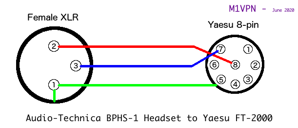
XLR end connections
Pin 1 - Shield that is connected to the 8-pin connector body.
Pin 2 - Signal +
Pin 3 - Signal -
Place wire between XLR connector ground and XLR pin 1.
Note: Disregard the capacitor in the following pictures. This was to prevent RF noise, but it actually created a filter on the audio chain ! Removed in final implementation.
Test shield continuity between XLR Pin 1 and the 8-pin connector body.
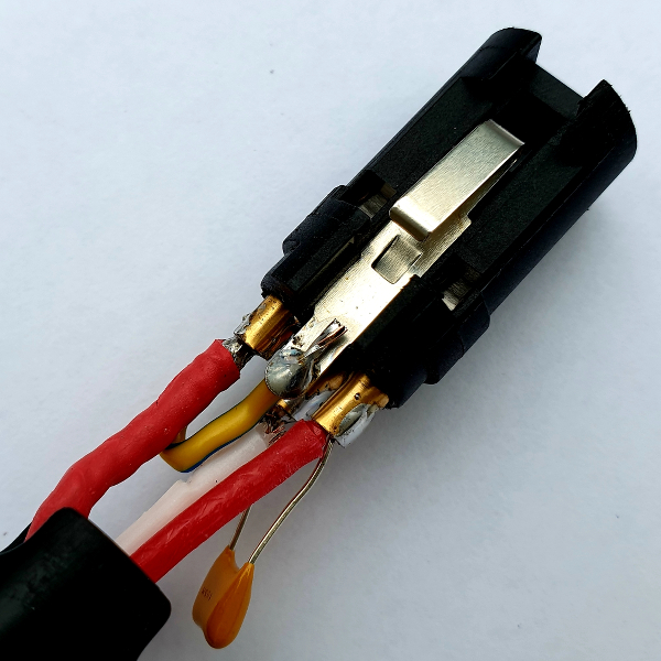
Base of connector showing Shield to Connector ground (excuse the soldering on test connector, still works though)

Top of connector, showing capacitor and top of ground loop. (This soldering is even worse, still works though)
FT-2000 Mic Gain setting - 85, but this may change when the EQ is set up.
Behringer Mixer Output to Yaesu Rear connector (incorporating Line to Mic Level Attenuator - -40dB)
This cable is a 6.35mm mono cable from the mixer to the rear Phono mic connection into the FT-2000. This is expecting a mic level input, whereas the output of the mixer is Line level. A -40db attenuation is required, so a L-pad is created from 2 resistors to drop to a 10th of the originating signal. This should level the microphone input.
In this case, an already terminated cable was purchased, with a Neutrik barrel connector, which has plenty of room inside to hide away two resistors and a capacitor, with careful soldering and heat shrinking.
The final solution is an L-Pad with an 680 Ohm and 68K Ohm resistor, as follows ;
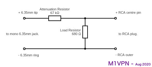
Why a 680 Ohm resistor for the output, well that is the input impedance of the mic connector on the back of the Yaesu FT-2000.
This forms the Pad part of the homebrew isolation box between the Outboard Audio equipment.
This cable did introduce some hum in testing, but I had poor grounding, so Your Mileage May Vary with this, but as the next cable is so easy to make, I'd go for that anyway.
It's not that I didn't want to buy a W2IHY i-box, but I had some bits and pieces and I enjoyed the challenge of building all my other cables. I'm not claiming that my implementation is better, but it was a product of experimentation, which for me is what Amateur Radio is all about, and why I got a licence in the first place.
The basic implementation presents the basic functions of Attenuation and Isolation. The circuit gives -35db attenuation which results in the FT-2000 Mic Gain being 29 with the Behringer Mixer set at 0db on the main output, +4db from the line.
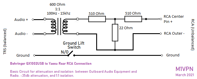
The main purpose for this circuit is to attenuate the signal from the Mixer to the front end of the radio. (Via the Mic port in the rear of the FT-2000, Mic Socket on the FT-847) Isolation between the Radio and the Audio kit, and reduce some Hum and RF being passed into the audio was also a requirement.
The Transformer is rated between 100 Hz to 15 KHz, but may swap it out for something better in time, or re-engineer a DI box.
A note for the FT-2000, the rear port is live with the front port in the menu settings. There should be no need to change anything for the rear port if you are using the front one currently. Both Mic ports are also live, so a mic without PTT will also provide input if you have a mic in the front as well as the rear.
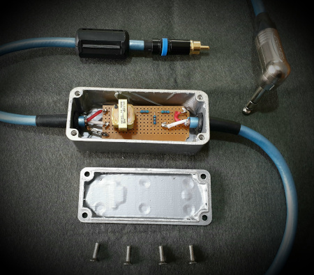
Completed Cable Assembly
8-Pin to RCA Extension Cable (For above)
