Uncategorised

Vaisala CT12K Celiometer
This device uses dual optics and a Class 1 Laser to identify cloud conditions using backscatter principle. The Laser used is invisible to the naked eye.
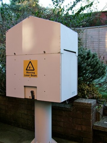
The CT12K uses a dual lens arrangement to determine cloud base height; one optical path for the transmitter and a separate optical path for the receiver. The operating wavelength of the Gallium Arsenide pulsed laser diode transmitter is 904 nm. The CT12K is equipped with a heater and blower housing to prevent snow and ice accumulation on the windows of the instrument cover. The model CT12K has an advertised maximum reportable cloud base detection range of 4000 meters (12,000 ft) above the surface. Initial tests have shown some interesting results, where cloud can be seen changing before a weather event occurs such as showers etc.
Unfortunatly, we have found an issue with the power supply on the CT12K and are awaiting news on a replacement / repair. The receiving script has now been re-written to use a Ubuntu Linux Server as it's host, taking the raw serial output and processing it, sending results to a mysql database. The CT12K will be back on-line when the power supply issue is fixed.
The Combe Raleigh Offset Centre Fed Antenna, design and build
I had grand plans for this antenna in 2012 when I first moved to this QTH. I bought the Baluns, Wire, Poles and antenna hardware, and promptly left them in the boxes until July 2020. I had MMANA GAL designs and plots galore, no antenna though.
I made do with the Hustler 6-BTV for 8 years until I was playing with my portable Inverted V for 20 metres in the garden and switching between this "two wires and a fishing pole" and the 6-BTV was marked. This prompted me to finally get on with this install.
Design
As the site suited an Offset fed antenna, the Fritzel FD4 was a good fit therefore was used as the basis of this antenna. Using the standard 33/66% offset from centre to locate a 200ohm feed point impedance and terminating with an 4:1 balun, this seems the ideal design for the site. The antenna has the following requirements :
- Power handling of 400w (UK Legal Limit)
- Antenna being Omni-directional, or biased to E-W.
- Able to handle high duty cycle modes (PSK31 / SSTV / FT8)
- Complement Hustler 6BTV vertical coverage
- Provide some level of NAVTEX reception on 518 Khz
The initial cut length to be used is the 28.43m / 13.76m split, to then identify the 200 Ohm feed point, thus 4:1 insertion point.
Components
- DX Engineering Maxi-Core® HighPower DXE-BAL200-H10-A Current Balun 4:1
- DX Engineering Maxi-Core® Feedline Current Choke FCC050-H05-A 1:1
- DX Engineering Antenna Support Cord
- DX Engineering End Insulators
- SSB Ecoflex 10 Plus Co-axial Cable
- Nevada Kevlar Antenna Wire
- Existing Push up Pole 12m
- Palstar AT-2K Antenna Tuner

Location
The antenna location is pivoted around the 12m push up mast, holding the substantial DX Engineering Balun and Antenna Centre. This extends two legs of weaved antenna wire (Kevlar Centered) of 28m and 13m between two trees. The tree points are as high as they will go with the centre at 7m (35ft is the best height for a 4:1 Balun)
A drop cable of Ecoflex 10 Plus, to a DX Engineering Feedline choke of 7m, and a run of 15m of Ecoflex 10 Plus into the Palstar AT-2K Tuner.
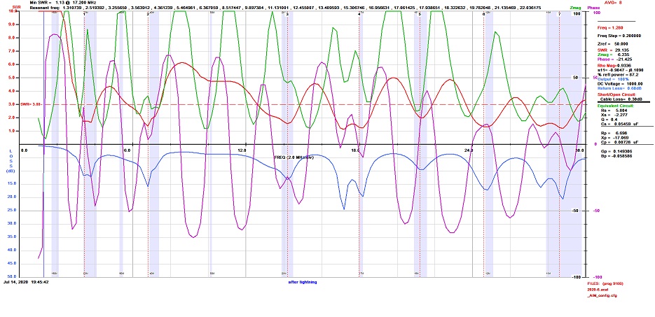
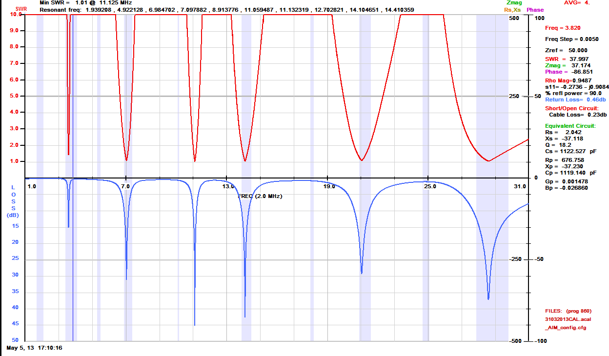
1 - 30 Mhz Band Scan
3D Modelling Plots
As can be seen from the models, the antenna works well for the main bands. With the AT-2k tuner, it can be made to tune from 160 to 6m, but as can be seen from the 160m plot, it has an undesirable plot of an NVIS antenna. This is corroborated by the stations worked on that band, with all being short DX stations.
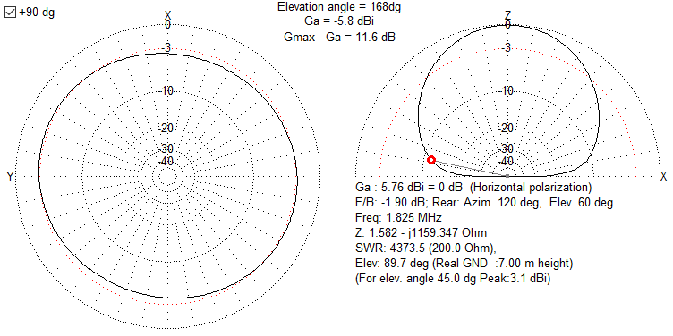
160m - AKA the Cloud Warmer
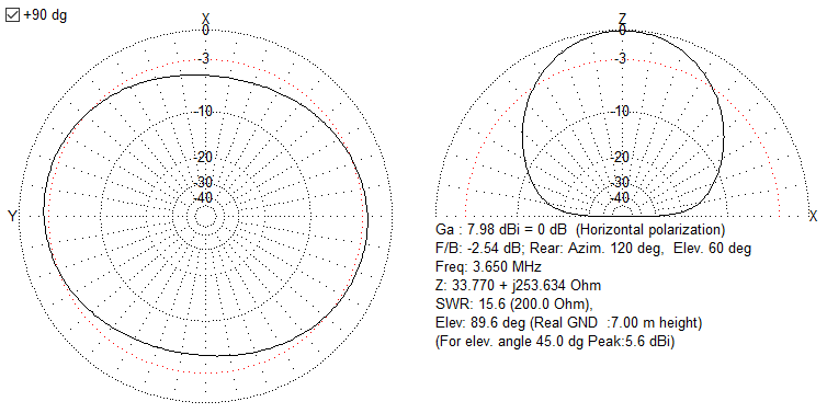
80M
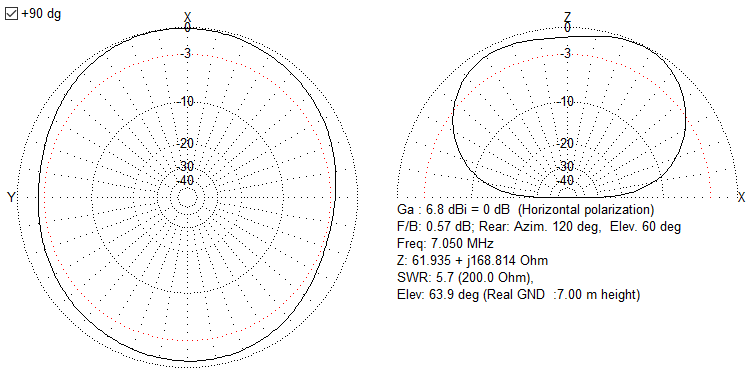
40M
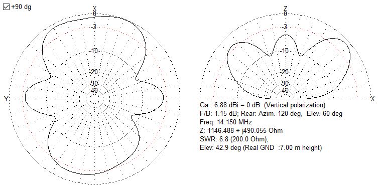
20M
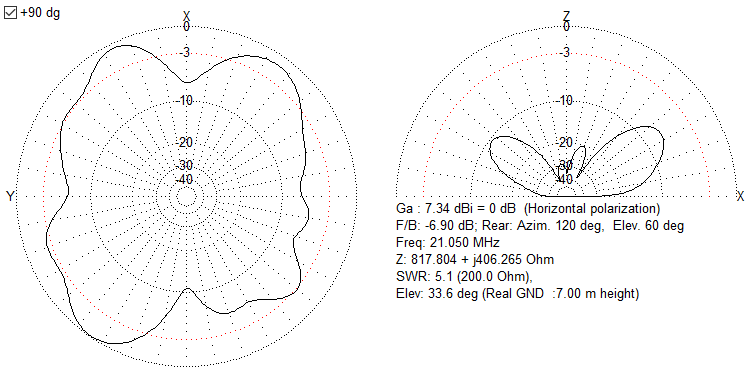
15M
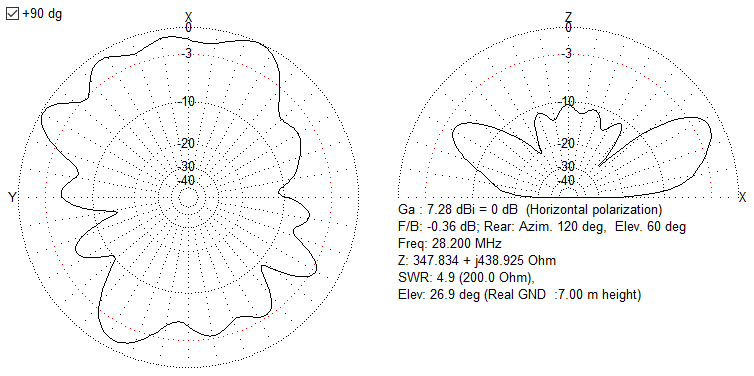
10M
Initial Performance
I still can't get over the difference between the two antennas, obviously, the polarisation should account for -3dB but the signal meter on my FT-2000 tells me otherwise. I note the difference in audio more than the signal strength, and sometimes the signal is lower in quantitative terms but better in most signal quality reception. I will work with the antenna more over 2020 to get a feel for performance outbound. It feels better from the number of stations responding to my FT8 CQ calls anyway.
The OCFD tunes well on the bands, although as you can see on the scan above that I can operate on a number of bands without a tuner, or well within the Auto-tuner in the radio. (Rarely use that as I've got a Palstar AT2K)
Received audio is noticeably stronger, Noise is largely less on the OCFD vs the Hustler 6BTV, with some noticeable exceptions of local electrical interference, but I can now switch polarisation with a flick of a rotary switch.
On FT-8, a station can be up to 2 S Points better on the OCFD, and on 80m Phone, stations that are 1-4 S points on the vertical, are 9 to +20db on the OCFD.
I'm happy with this antenna, as part of my station !
Update - Jan 2021
The antenna continues to perform very well and has exceeded what I wanted. I managed to tune on 160m, and whilst the MMANA model and the resulting WSPR results confirmed a NVIS antenna (Cloud Warmer), I soon racked up 25 DXCC on FT8 just as an experiment. This was a bonus band for me, so if I can use it for local 160m QSO, I'm fine with that.
The next experiment is to raise it from 7m at the centre to 12m as I have noticed that performance drops sharply when it is lower down.
80, 40 and 20m continue to be well above 2 S points from the Hustler Vertical, and 30m works well also. The WARC bands don't do as well but I don't use much apart from 17m and the Hustler vertical works ok for those.
10m, I now have 3 choices with the OCFD, Hustler or Antron 99. The OCFD is the best performer, the two verticals are very similar.
6m, I have awful QRM from PLT so have to sort that, No antenna works on that band here.
4m, that works fine but is Horizontal when the local stations are all vertical. It tunes though !
Installation and working of the Hustler 6BTV Vertical
Having been located at a previous QTH due to a small garden, the 6BTV has made it's way to Combe Raleigh where it has been the first antenna to be installed.
Parts
- Hustler 6BTV
- DX Engineering - DXE-VFCC-H05-A
- SSE Ecoflex 10 Plus Co-ax
- Galvanised 1 3/4 inch Pole
- Postcrete Concrete
- Stone Chips
- Pressure Treated Wood
- Weed Membrane
The DX Engineering balun is a isolating balun to reduce the reflected RF into the Co-ax which is specially designed for HF Verticals. Due to the limited radials I will be installing, this can only help with reflections. The serious upgrade in Co-ax is to ensure that every bit of RF ends up in the antenna, and on receive I get every milliwatt I can. Expensive, but good.
The Permanent Install
The install of the Hustler 6BTV has been a long time in progress, but finally finished.
Mounting Pole
In line with the DX Engineering advice the pole is a galvanized 1 3/4 inch pole, 1.5m in length, with 60cm above ground. A 8 inch diameter hole was dug and filled with postcrete, drainage rock at the base. This was hammered into the base rock about 30cm.
Radial Field
As with all verticals, the need for radials to make the antenna balanced and performant. For this, 100m of galvanized electric fence wire was buried on the 180 degrees that I can install. These are of random lengths, to fill the lawn space. This is terminated onto the U-bolts which clamp the Antenna base and will be replaced with a home built radial rack when time permits. The DX Engineering Radial Plate is a good product, but with only using 180 degrees available, buying one would be a waste.
Vertical Balun
To assist with feed line currents induced into the co-ax from the radiating element, the VFCC-H05 is especially configured for the Hustler 6BTV, but will work on other verticals. Whilst I do have a radial field to reduce this phenomenon, I do only have 180 degrees due to the proximity to the house.
DX Engineering Vertical Matching Network
This does increase the bandwidth a small amount and drops the SWR on the 80m Band. Easily configured, and gives a good few Khz, but still not the whole band.
Tuning the Antenna
As this antenna changes it's characteristics when the radial field is connected, the tuning has been left to the final install. The work is somewhat easier to do as I have an AIM 4170C Antenna Analyser which helps no end.
Following the DX Engineering guidance, only the 10m and 40m traps needed to be moved, and only 1 inch each. The antenna tuned well, and the plots are shown per-band later on this page.
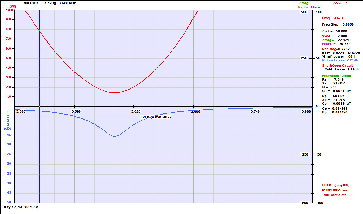
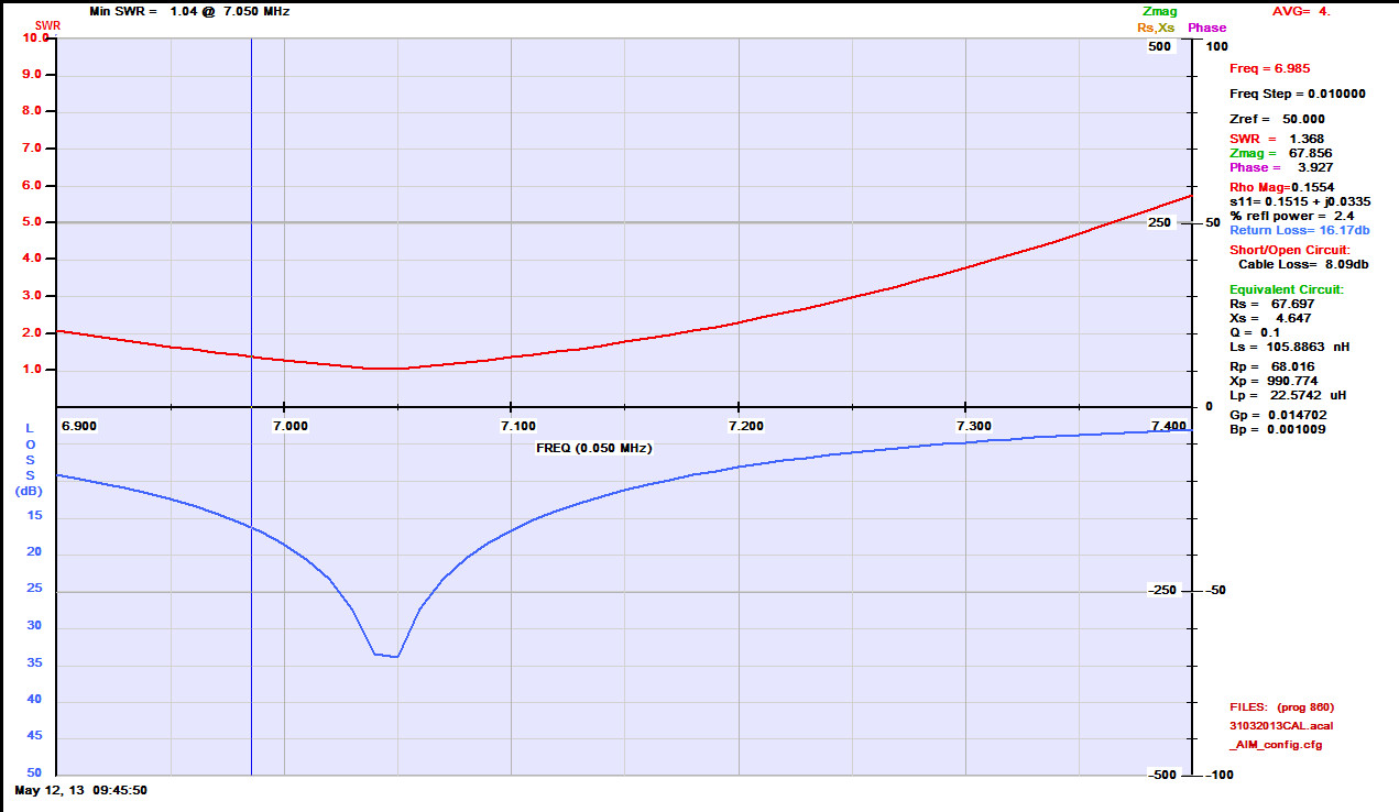
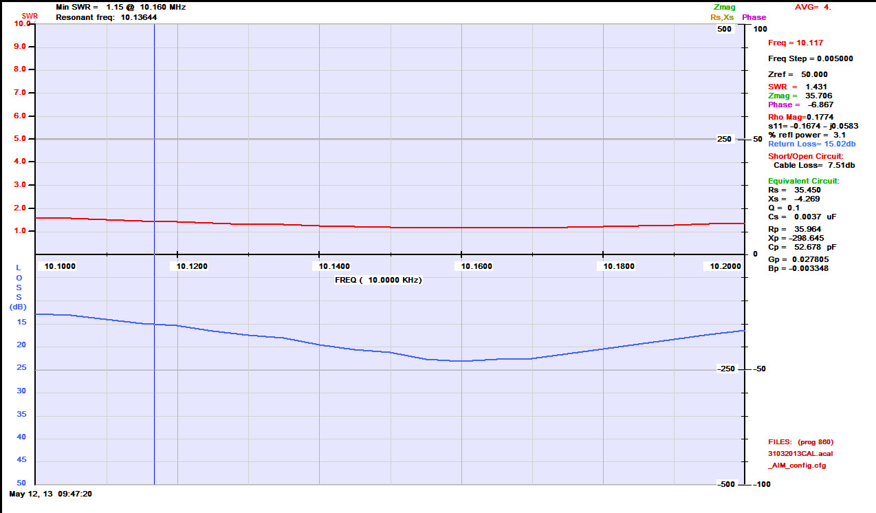
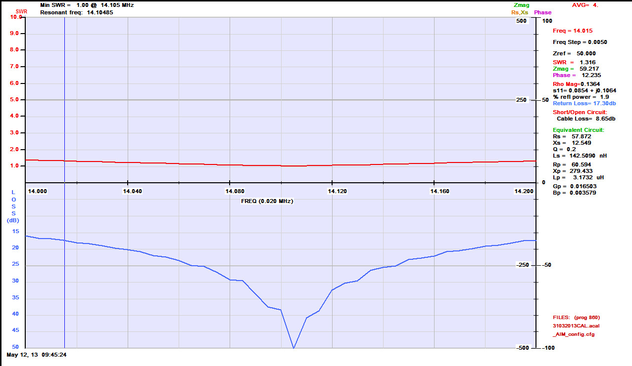
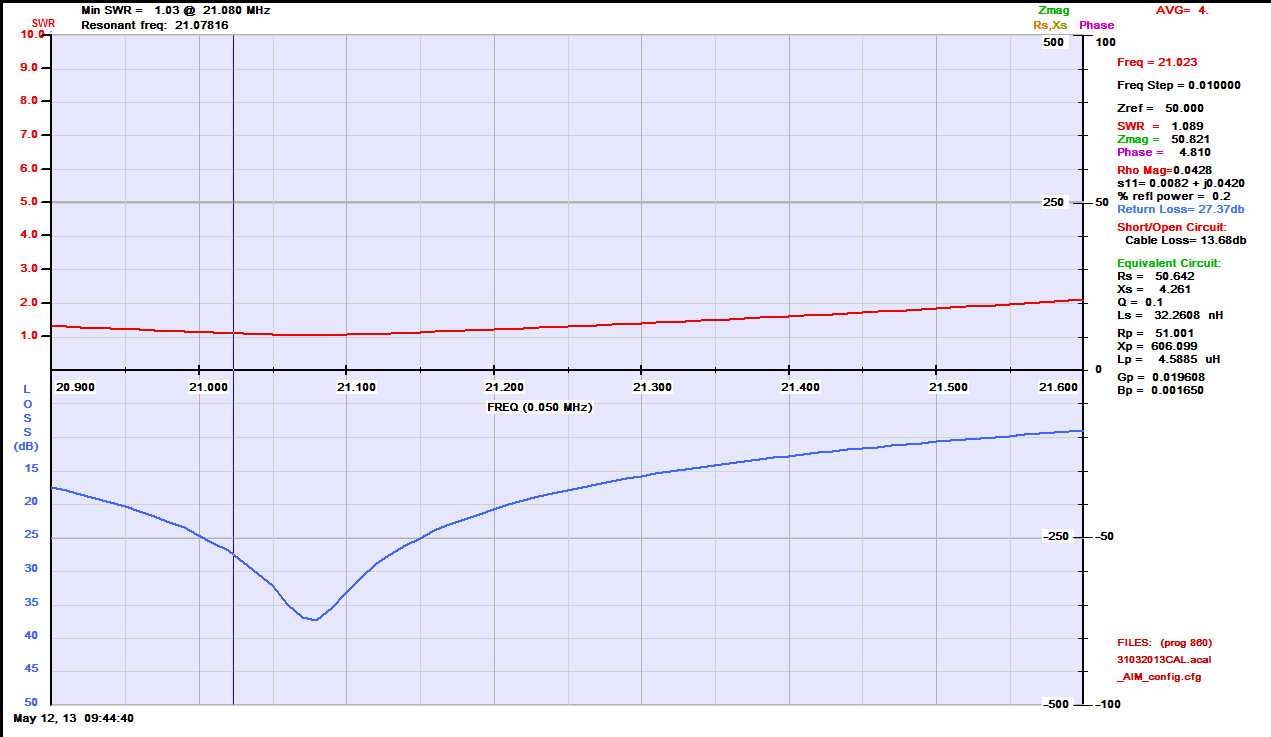
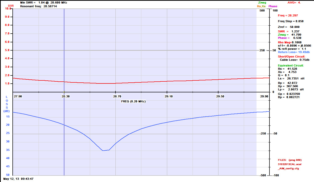
Plots generated by AIM 4170C Antenna Analyser - Supplied by Array Solutions.
Getting started with Packet - AEA TNC
Buying a PK-232 TNC
I'd often seen the PK-232 in shack photos, E-Ham and QRZ.Com classifieds so it was natural to get one as these were highly regarded back in the day. The natural hunting ground was ebay, and whilst these come up in the US regularly, the UK ones are not so prevalent.
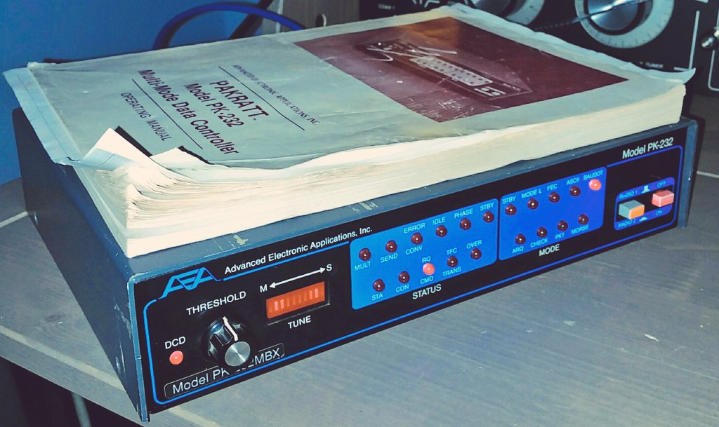
I managed to successfully bid for a later PK-232, which was sold as status unknown so was a small risk, although the pictures showed the Baudot LED lit, which could indicate that it booted properly.
This promptly arrived in the original box, manuals and the paperwork for the upgrades from Timewave, namely the CMOS Low Power kit. This was working from a TNC perspective, however this had a dry joint on the Threshold control, which is a 1K ohm Linear Potentiometer. This was replaced.
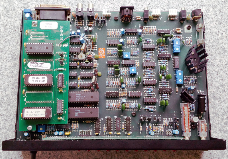
I then got notified of another PK-232 on ebay, but this one had the MBX upgrade but was cosmetically in worse shape. This was worth bidding for, just for the MBX upgrade, and anything else it had on it. It was an early unit originally, much younger than the one I had previously bought, however this was also in an unknown state.
It arrived, this time with just the manual and some printouts from Timewave's Website back in 2003. Promptly plugged in, this had been upgraded with the MBX daughterboard but was only on the 6.8 version firmware, so no PACTOR, but ready for v7.2 should I acquire it. This unit worked 100%, and was happily decoding RTTY and Morse from the bands.
Cables and interfaces
Always a but of a challenge, Serial Comms back in the day were difficult at the best of times, but I've not had a RS232 jumper box for years and with varying information out there on TNC Serial comms, I set about building a proper cable with hardware handshaking. Whilst the simple 2,3 and 5/7 would make it work (and did just to check the units initially) I wanted the full 1-8 +20 configuration.
Looking through the junk boxes, I found a nice 2m SCSI cable with a 25 pin D connector on one end, a Full SCSI on the other. Shielded and good copper content cables, the wire cutter sliced off the SCSI interface and replaced with the 9 pin D needed to connect to the PC end. A quality Die-cast shell from Tronicized made a robust connector.
My Shack PC still has a single 9 pin serial connector, but I would now need more so an additional card from Startech was procured. I only use Startech peripherals, as they just work and have great support if things don't work out, which is actually more important.
The Audio cables, which for a Yaesu FT-847 is always a challenge because it has two connectors for Packet, and requires additional components to make it work which means that you can't just wire it up ! The HF connector is the one that I wanted to use first, so I set about making a 5 pin IDC connector to Stereo 3.5mm Jack, with a Cap/Res wired in appropriately for the radio. The 5 pin IDC that came with the PK-232 are long gone, and no longer easily available however the 5 pin IDC from Motherboard USBs are available, again from Tronicized which enabled the cable to be completed. (See HF Cable Page - HF AEA PK-232 to Yaesu FT-847 )
The VHF Packet connector on the FT-847 uses a 5 pin mini-DIN connector, and I had one in stock from a soundcard project. (See VHF Cable Page - VHF AEA PK-232 to Yaesu FT-847 )
On the Air
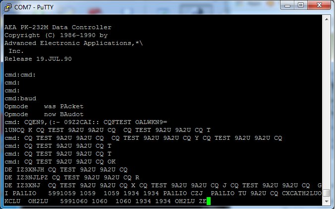
The Radio was connected up and the TNC switched on. The lights flickered and the Baudot LED lit. PuTTY was configured on COM7 to 9600 8 N 1, and the PK-232 put two lines of "Junque" characters, by typing a few *, (Shift and 8) This will prompt the PK-232 to auto baud rate to the client.
The output will then be in ASCII, and display the PK-232 boot sequence with Firmware versions etc.
Putting the PK-232 into Morse, by typing MO, then tune the radio to find a loud CW signal which resonated in the Mark/Space indicator with the DCD LED only just lit by adjusting the Threshold control, found the CW QSO's being displayed on the screen. Issuing the BA command, and tuning for a RTTY signal found the same output.
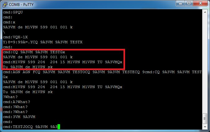
Issuing the X command put the radio into transmit, and the typed words were then RTTY encoded out of the radio. CTRL+D to put the PK-232 back into Receive mode.
First QSO
On the 13th May 2018, 30 years after the PK-232 was built, I made a QSO on RTTY (Baudot) with 9A3VM. It was'nt the easiest RTTY QSO i've had but I managed a two way communication ! Not having Macro's, and auto stop and start transmissions was tricky but once I'd worked out that I needed to monitor my communication outbound, it became easier.
Receiving NAVTEX
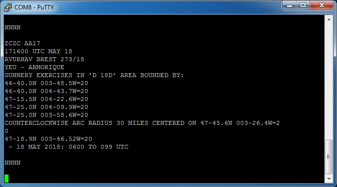
One of the first additions to the firmware on the PK-232 was the ability to receive NAVTEX an WeatherFax. The former is a dedicated mode, which configures the unit to decode the text and display on the console. This signal is transmitted worldwide on 518kHz and can be used as a beacon receiver to see how conditions are on the low bands.
Issuing the NA command, sets the PK-232 to NAVTEX receive with Dial Frequency 516.600Mhz USB
Frankenstein's Monster
As described above, I had an early, cosmetically poor PK-232 with a MBX upgrade and a good condition PK-232 with the Low Power CMOS upgrade which is a later edition, but needed a new threshold control.
I intended to make 1 out of 2 here, with the later cosmetically sound PK-232 having the MBX upgrade moved over from the older one with a new Threshold control Pot.
First fix was the Threshold control, and sourcing a through hole 1k Ohm Pot from CPC, and whilst I was at it, a replacement CR2032 battery holder to replace the 3x 1.5v battery box in the top of the lid, if I need to use it which is similar to the Timewave upgrade.
Next, the move of the MBX board, which required the jump lead to be de-soldered from the resistor and placed on the newly removed U2, 3, 4 & 5. This was straight forward, and the firmware moved over with no problems.
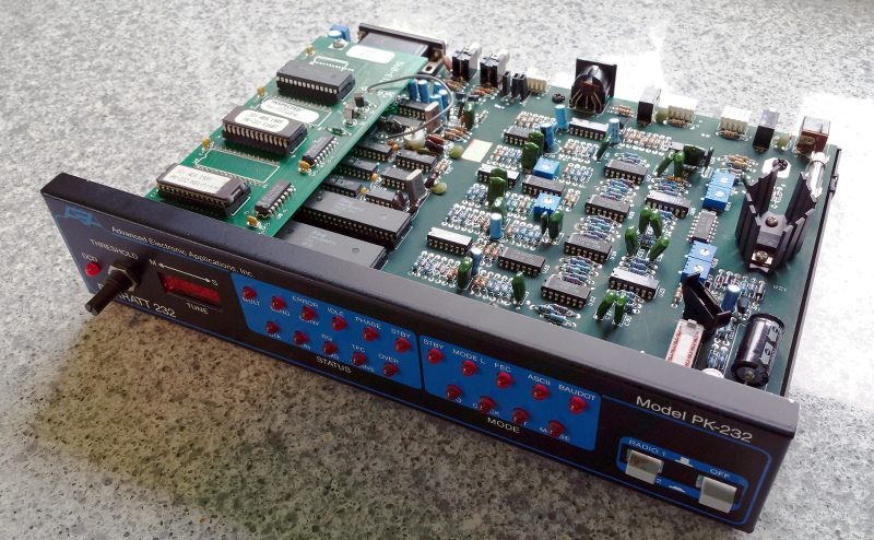
Newer PK-232 and MBX located
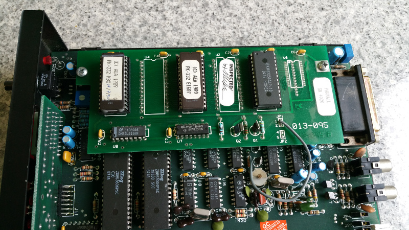
MBX Daughter Board
Upgraded to 7.2 firmware, which includes PACTOR version 1 and a number of software fixes and enhancements.
What happened next ....
With all things, it was bound not to be a straightforward happy ending. I made some Packet QSO's, but there seemed to be a tones issue and also it just did not perform for transmit, receive was excellent, often decoding packets I didn't even hear, but I gave up for a bit. I then stumbled across the CAL function in the manual so decided to do a tune up, which turned out to be another bunch of issues but it got me to the end, somewhat.
Ignore Online Information if it doesn't make any sense, I wish I had done that but learned the hard way. There are no Schematics for the Euro model, and following one for a US model means you might swap components you don't need to. I did, and it made no difference anyway.
The main outcome is that my PK-232 is a Euro Spec model and therefore the tones are set up for 1250/1450 spacing. This would account for the weird CF settings and Dial Freq that I had to use. It also accounted for why, when I tried to get it to work on the US tones, the Pot's would not go that far, even after I swapped them out, thinking they were faulty ! Now, back together and set up, it's on the air with a suitable CF for Network 105.
14.103.3 - CF
1250/1450 - Tones
LSB Dial Freq - 14.104.650 Mhz
Now this is all done, I'd better get started on the PK-900, and that is a complete mess already. I've been asked about why I keep spending time on Hardware when Soundcards can do all this, and the reply is simple. It is because these are interesting modes, supported by interesting hardware. I've got a soundmodem loaded, but the LED's, the quirky cables and the EPROMS make it more fun.
There's also a DSP-2232 on ebay tempting me, But I must resist !
See you on the Terminal ...
